5L30.10 • Filters and Rectifiers — AC: Bridge Rectifier & LC Filter
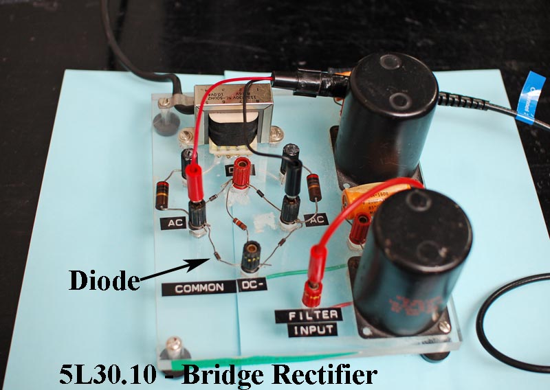
Photo Shows the Demonstration Apparatus Used by the University of Texas at Austin.
Instructions / Notes:
- Demonstration includes an oscilloscope with a VGA output and a rectifier circuit board that has the option of adding two LC filters..
- Note: This demonstration requires the use of a VGA cable in order to display the screen through the A/V system.
Starting points:
- The above photo shows the two oscilloscope test leads plugged in to the AC inputs at the start of the demonstration.
- The oscilloscope should be already set to its DC coupling mode.
- The voltage adjustment is set to 2 volts per division.
- The horizontal adjustment needs to be set to 5 milliseconds.
- This old Tektronix scope requires a full minute to boot up.
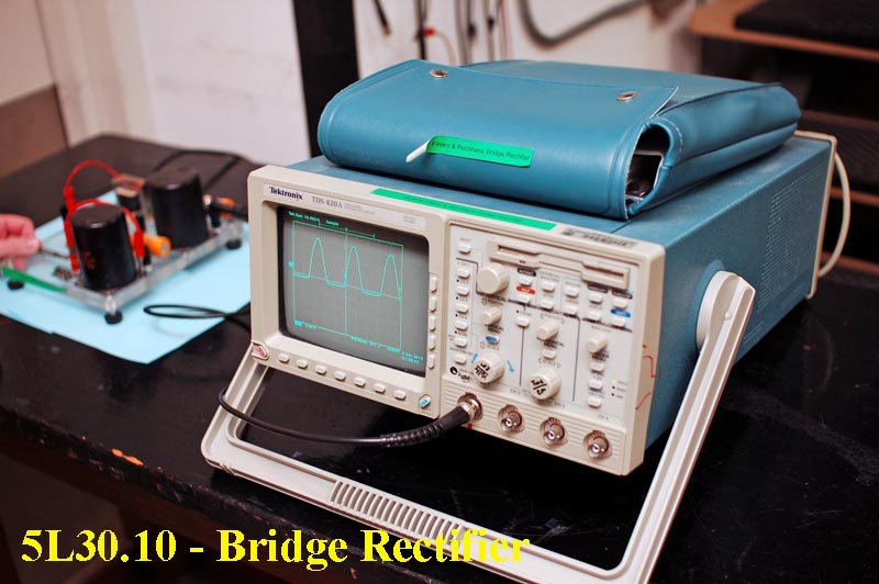
Photo Shows the Apparatus Used by the University of Texas at Austin after the initial 1 minute start up.

- Half wave verses full wave rectification can be shown using the output of 2 diodes verses all 4 diodes on the bridge board.
- To show half-wave rectification, just move the "red" oscilloscope test lead to the top terminal of the rectifier.
- To show full wave rectification, move the "black" oscilloscope test lead to the bottom terminal of the rectifier circuit.
- The fully rectified wave form fills in the gaps of a half way wave form - but is very ripply.
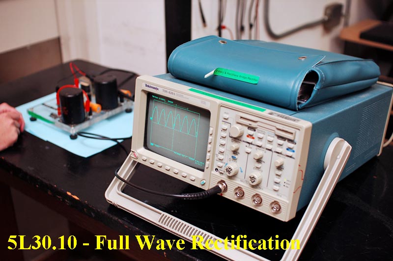
- The probes from the scope can then be hooked up to filter out most of the ripple in the above wave form by using either one or two LC filters.
- Plan to come early to practice this part of the demo, if you are unfamiliar with this equipment.
Last updated on August 30, 2017