4F20.10 • Stirling Engine Model
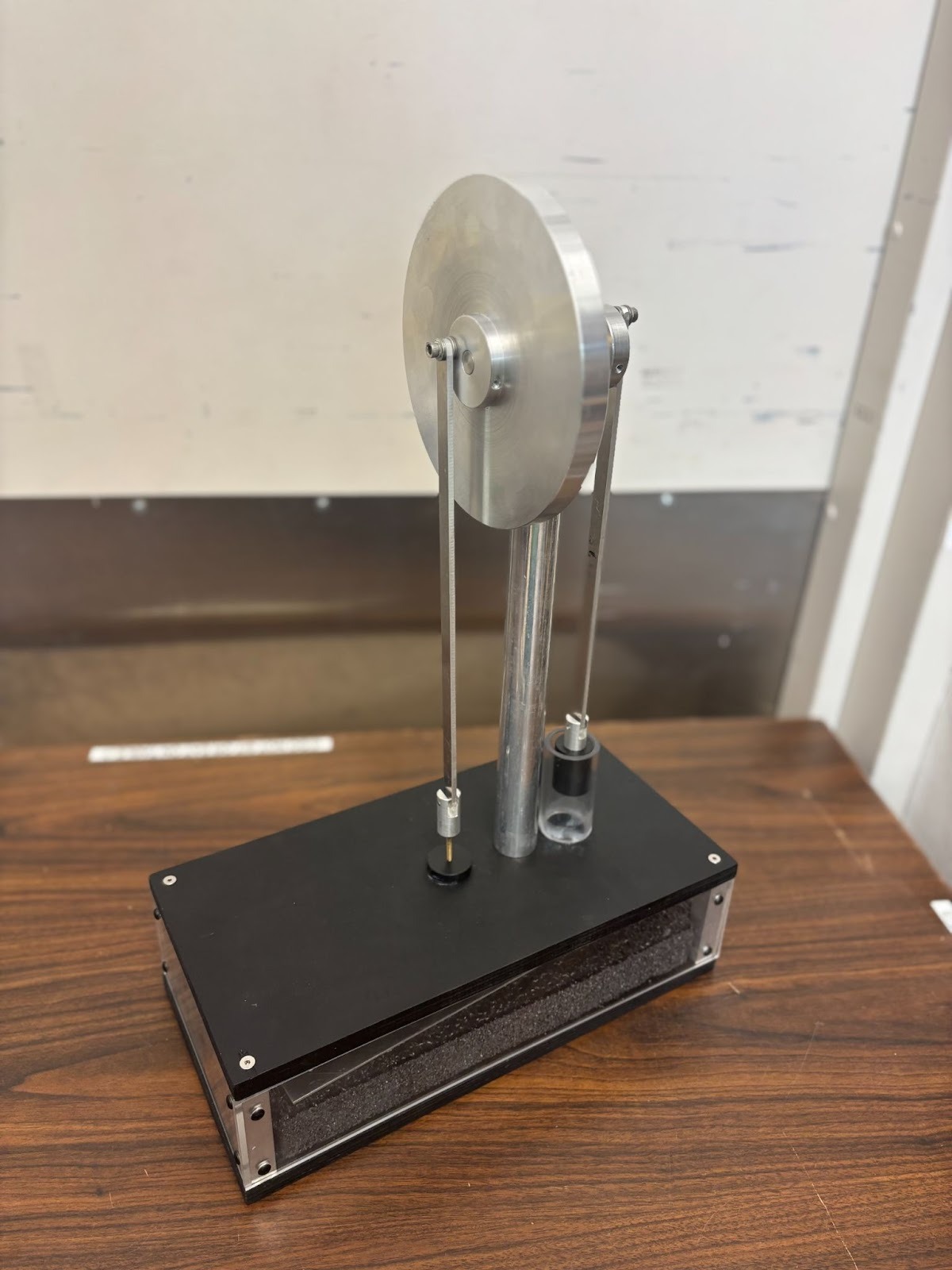
Photo Shows the Apparatus Used at the University of Texas at Austin
Concepts Conveyed:
- This Stirling Engine model demonstrates core operational principles of the Stirling Engine that are better visualized for clear understanding, like the Stirling cycle, heat transfer, pressure variation, and energy conversion.
- Although it is not a fully functional Stirling Engine, it brings theoretical ideas into practical application for its role in sustainable energy systems.
Instruction/ Notes:
- Show the audience the full model:
- Large ring = Flywheel
- Box = Displacer Base
- Foam in box = Displacer
- Black cylinder in plastic cylinder = Piston
- Rotate the Flywheel to show the main processes of the Stirling Cycle: Compression, Heat Addition, Expansion, and Heat Rejection
- When the displacerr is near the top of the base, most of the gas is exposed to the heat source and expands
- Since pressure increased, the power piston will push up
- When the displacer is near the bottom of the base, the engine gas cools and contracts, decreasing pressure and allowing the power piston to move down
- This is the non-functional version of the Stirling Engine, the smaller Stirling Engine functions!
Staff Notes / Tips:
- This is a structural model only; it doesn't simulate a working Stirling Engine
Last updated on November 19, 2025